Rotary Gap Construction Details
Rotary Gap Construction Details
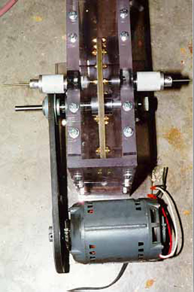
- Side Plates -------------- 1" thick acrylic, 14"x14" square
- End Plates --------------- 1/2" thick polycarbonate
- Base Plate --------------- 1/2" thick polycarbonate
- Rotor (disk) ------------- 1/2" thick G-10 (Epoxy-fiberglass composite)
- Shaft ------------------- 1/2" electric motor shafting
- Stationary electrodes ---- 1/8" TIG welding electrodes
- Electrode holders -------- turned aluminum
- Electrode holder holders - turned phenolic resin plastic (bakelite)
- Bearings ----------------- Sealed ball bearings
- Pulleys ------------------ Salvaged from furnace blower
- Electric motor ----------- (Not the one shown on any photos) 1 HP 10,000 RPM
Carter motor 110v AC/DC
- Moving Electrodes -------- 24 1/4-20 Brass Acorn nuts (2 each side)
I designed the rotary gap mechanism this way so that it would satisfy several
requirements.
- Ability to change motors relatively easily
- High electrode velocity
- High break rate
- Bulletproof enclosure to contain exploding disks, etc.
- The electrode holders must be able to get extremely hot (300F, ~175C)
- The electrodes must have adequate heat dissipation available.
- Variable speed
To achieve these goals, I opted for a totally enclosed disk, and selected
materials that wouldn't be affected by the heat that they would encounter.
The large motor shown in the photos is not the one that I finally settled upon.
It was single speed induction motor, and therefore I could not adjust its
speed. I used it because it was handy and I had no other motor at the time.
The motor that I am using now is much more powerful and faster as well. I can
vary the speed of the disk from 0 to about 5000 rpm, which is more than fast
enough.
Because the electrodes would get hot when running at high power levels, I
decided to hold them with large aluminum holders. They are turned from 1.5"
aluminum rod. I was also concerned that they would get hot enough to soften
the acrylic side plates. To get around the problem, I made some phenolic
bushings from pieces that I had around the garage.
I have used this rotary gap in coil operation and it works quite well. It is
quiet, which is Oh So Important when running a tesla coil :-) (In case you
aren't aware of it, a tesla coil is extremely noisy.)
Return to main rotary gap page
Return to homepage
This page has been accessed
times since 3/2/97 and was last updated
.